

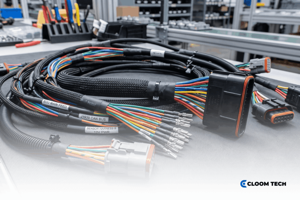
Ampacity is the maximum continuous current a conductor can carry at a specified ambient temperature without exceeding its insulation’s thermal limit. Get that number wrong in either direction, and you pay for it. Undersized wire dissipates excess energy as heat, raising conductor temperature until insulation degrades or the circuit fails. Oversized wire avoids that risk but adds unnecessary cost and weight.
This wire ampacity chart covers AWG gauges from 28 to 4/0, with NEC 310.16 reference values, derating factors, and aluminum-versus-copper comparisons for harness specifications.
What is Wire Ampacity?
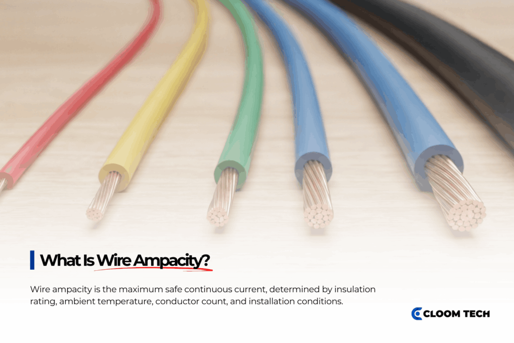
Wire ampacity is the maximum continuous current a conductor carries without exceeding its insulation’s rated temperature. NEC 310.16 ampacity values assume a 30°C baseline ambient, three or fewer current-carrying conductors, and a defined insulation type. Changing any of those conditions alters the usable current capacity.
Ambient temperature and insulation rating set the thermal ceiling for a given conductor. Bundle count and installation environment determine how much heat builds up before the conductor reaches that ceiling.
AWG Ampacity Chart (NEC 310.16, Copper, 30°C Ambient)
NEC 310.16 sets copper conductor ampacity at 30°C ambient with no more than three current-carrying conductors under bundled installation conditions. Apply derating factors from the sections below before specifying for a harness build.
| AWG | Area (mm²) | Resistance (Ω/1,000 ft) | Ampacity 60°C (A) | Ampacity 75°C (A) | Ampacity 90°C (A) | Typical Harness Use |
|---|---|---|---|---|---|---|
| 28 | 0.08 | 64.9 | — | — | — | Fine signal, instrumentation leads |
| 26 | 0.13 | 40.81 | — | — | — | Low-level sensor signal |
| 24 | 0.20 | 25.67 | — | — | — | ECU sensor, data bus |
| 22 | 0.33 | 16.14 | — | — | — | Control signal, CAN node wiring |
| 20 | 0.52 | 10.15 | — | — | — | Logic-level, low-current actuator |
| 18 | 0.82 | 6.385 | — | — | — | Lamp control, LED driver output |
| 16 | 1.31 | 4.016 | — | — | — | Relay coil, small actuator feed |
| 14 | 2.08 | 2.525 | 15 | 20 | 25 | Solenoid valve, relay output |
| 12 | 3.31 | 1.588 | 20 | 25 | 30 | Accessory power, HVAC blower circuit |
| 10 | 5.26 | 0.999 | 30 | 35 | 40 | Motor lead, high-current accessory |
| 8 | 8.37 | 0.628 | 40 | 50 | 55 | Heavy motor lead, winch feed |
| 6 | 13.3 | 0.395 | 55 | 65 | 75 | High-current DC link, starter circuit |
| 4 | 21.1 | 0.249 | 70 | 85 | 95 | Main harness power feed, large drive |
| 2 | 33.6 | 0.156 | 95 | 115 | 130 | Primary harness trunk, inverter feed |
| 1 | 42.4 | 0.124 | 110 | 130 | 145 | High-current harness main |
| 1/0 | 53.5 | 0.098 | 125 | 150 | 170 | Battery cable, high-load harness feed |
| 2/0 | 67.4 | 0.078 | 145 | 175 | 195 | EV power distribution, welding lead |
| 3/0 | 85.0 | 0.062 | 165 | 200 | 225 | Industrial equipment power feed |
| 4/0 | 107 | 0.049 | 195 | 230 | 260 | Main battery cable, traction harness |
Source: NEC Table 310.16 (2023 Edition). NEC 310.16 begins at 14 AWG; for gauges 28 to 16, consult SAE J1128 style ratings or your OEM specification. Values are for reference only and vary by installation conditions. Consult the applicable standard for your specific application.
The 60°C, 75°C, and 90°C columns correspond to common wire insulation styles like TW, THW/RHW, and THHN/XHHW, respectively. NEC 240.4(D) caps overcurrent protection for 10, 12, and 14 AWG copper at 30, 20, and 15 A, respectively. That limit applies regardless of the 90°C column rating.
For automotive primary wire, SAE J1128 publishes style-specific ampacity ratings for wire styles such as GXL and TXL. Each style carries defined current limits that account for thin-wall insulation and underhood temperature conditions.
NEC 310.16 provides a conservative baseline. Harness engineers typically adapt those figures using free-air conditions per NEC 310.17 or OEM-specific derating schedules for the target environment.
Aluminum vs. Copper Ampacity
Aluminum conducts at roughly 61% the efficiency of copper. For the same AWG ampacity, an aluminum conductor needs to be approximately two AWG sizes larger than its copper equivalent. Per NEC 310.16, a 1/0 aluminum wire has an ampacity of 120 A at 75°C, roughly matching that of a 2 AWG copper conductor. 4/0 aluminum wire ampacity reaches 180 A at 75°C, comparable to a 2/0 copper conductor at the same temperature rating.
| Property | Copper | Aluminum |
|---|---|---|
| Conductivity (vs. copper) | 100% | ~61% |
| Equivalent gauge for same ampacity | Baseline | ~2 AWG sizes larger |
| Weight per foot | Higher | Lower |
| Typical application | Harness wiring, control circuits | EV battery cables, power distribution |
| Termination complexity | Standard crimp | Requires antioxidant compound, compatible terminals |
Aluminum appears in high-current, weight-sensitive applications (EV battery distribution and power bus runs) but rarely in standard control harnesses. Weight per amp is where aluminum gains ground. A 4/0 aluminum conductor delivers 180 A at roughly half the mass of an ampacity-equivalent copper conductor, a meaningful tradeoff on long high-current runs.
Termination complexity limits broader adoption: aluminum oxide raises contact resistance at crimp joints unless the drawing specifies anti-oxidant compound and aluminum-rated terminals.
Derating Factors
NEC 310.16 AWG ampacity figures are ceilings, not targets. Those base values assume bundled or enclosed installation conditions (not free air). NEC Table 310.17 governs free-air single-conductor ampacity and yields higher values for the same gauge. Two corrections reduce the 310.16 figures for a real harness build, and both are multiplicative: apply them together.
| Current-Carrying Conductors | Ampacity Multiplier |
|---|---|
| 4–6 | 80% |
| 7–9 | 70% |
| 10–20 | 50% |
| 21–30 | 45% |
| 31–40 | 40% |
| 41 or more | 35% |
Ambient temperature derating (NEC 310.15(B)(1)) applies when ambient temperature exceeds 30°C. For 90°C-rated conductors: multiply by 0.96 at 35°C, 0.91 at 40°C, 0.82 at 50°C, and 0.71 at 60°C.
A worked example shows why both factors matter. A 10 AWG, 90°C conductor carries 40 A per NEC 310.16. In a bundle of 12 conductors at 40°C ambient, the derated capacity becomes 40 × 0.50 × 0.91 = 18.2 A. The example uses 90°C for simplicity; correction factors differ for 60°C and 75°C-rated conductors per NEC 310.15(B)(1).
Applying Ampacity to Wire Harness Design

Gauge selection in a custom wire harness build involves three independent constraints, and the largest conductor demand wins. Wire ampacity sets the thermal ceiling after derating. Voltage drop sets a separate floor on longer low-voltage runs. A 12 V or 24 V DC circuit at distance often requires a larger gauge than ampacity alone dictates. Mechanical requirements set a practical minimum: very fine gauges lack the robustness needed for crimp terminations on connectors rated for heavier conductors.
Bring your conductor specifications (load current, run length, and ambient conditions) to a DFM review before committing to a build print. Include your bundle count so the DFM review can account for the correct derating.
At Cloom Tech, we assess whether the specified gauges are appropriate for the application and flag any sizing concerns against IPC/WHMA-A-620 build requirements. Need help specifying the right wire for your harness? Get a free DFM review here.
FAQs on Wire Ampacity Chart
What is wire ampacity?
Wire ampacity is the maximum continuous current a conductor carries at a specified ambient temperature without exceeding the thermal rating of its insulation. NEC 310.16 tabulates ampacity at a 30°C baseline ambient, three or fewer current-carrying conductors, and a defined insulation class.
What AWG wire for 30 amps?
A 10 AWG copper conductor rated at 75°C carries 35 A per NEC 310.16 under bundled installation conditions. That figure assumes three or fewer current-carrying conductors at 30°C ambient. For a bundled harness run or elevated ambient temperature, apply the appropriate derating factors. The required gauge may step up to 8 AWG depending on bundle count and thermal conditions.
What is 4/0 aluminum wire ampacity?
4/0 aluminum wire ampacity per NEC 310.16 is 180 A at 75°C. That value assumes bundled installation, three or fewer conductors at 30°C ambient. At a 60°C insulation rating, 4/0 aluminum wire ampacity drops to 150 A. Apply temperature and bundle derating factors for any installation outside those baseline conditions.
How does bundling affect wire ampacity?
Bundling reduces wire ampacity because adjacent conductors generate heat that accumulates across the group. Per NEC 310.15(C)(1), the ampacity must be derated to 80% for four to six conductors, 70% for seven to nine, and 50% for 10 to 20. Apply the bundle factor and the ambient temperature factor together before comparing against the circuit load.
Back to Top : Wire Ampacity Chart: AWG to Current Rating for Harness Engineers
