
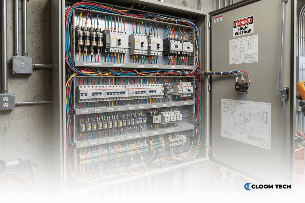
An industrial control panel rated below the site’s available fault current is a failure waiting to happen. When a severe short circuit hits, current can blow past the equipment’s tested withstand limit before the upstream breaker ever interrupts the circuit – and the damage is done in milliseconds.
That’s what the short-circuit current rating (SCCR) protects against. It defines the maximum current an assembly can safely tolerate under abnormal conditions. Getting it right ensures NEC® compliance, correct coordination of protective devices, and a proper match between equipment and the system’s calculated fault current. This guide covers what SCCR means, how to determine it, and where UL and IEC approaches differ.
What does SCCR Stand For?
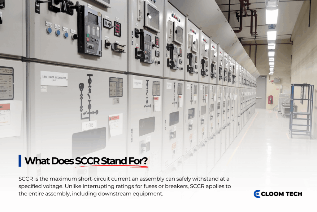
SCCR stands for short-circuit current rating. It’s the maximum short-circuit current a component or assembly can safely withstand at a specified voltage.
Here’s the key distinction: an SCCR applies to the whole assembly, not just the protective device. That’s different from an interrupting rating. A fuse or breaker might clear a dangerous current cleanly, but the downstream equipment still needs its own verified rating to survive the same event.
Why SCCR Matters in Today’s Systems
Modern facilities run with far higher available fault current than older installations, and that puts more stress on every control panel in the system. A properly matched SCCR buys the equipment enough time to survive a severe event while upstream protection clears the circuit. In practice, that means it helps you:
- Prevent equipment failure when available short-circuit current exceeds the assembly’s tested capability.
- Stay NEC-compliant by matching the marked SCCR to the installation’s calculated current levels.
- Limit damage inside the panel during severe short-circuit events.
- Protect personnel from enclosure rupture and potential arc flash exposure.
- Preserve nearby infrastructure during high-energy three-phase faults.
- Avoid welded contacts and damaged components caused by an inadequate rating.
Standard SCCR Ratings: UL vs IEC Frameworks
UL 508A and IEC standards get to SCCR by different routes, but both insist that equipment protection match the calculated available fault current for the installation. Here’s how the two compare:
| Framework | SCCR Approach | Protection Method | Coordination Method |
|---|---|---|---|
| UL 508A | Requires a marked SCCR value for each control panel assembly | Applies default values from Supplement SB Table SB4.1 when components lack markings | Uses tested combinations under UL 508A Supplement SB |
| UL framework | Allows higher effective SCCR through tested assemblies | Uses current-limiting devices, such as a current-limiting fuse or tested breaker combinations | Verifies protection through approved assembly testing |
| IEC 61439 | Declares conditional withstand capability through Icc values | Requires a specified upstream protective device, such as a defined gG fuse | Relies on type testing or verified design rules |
| IEC coordination | Defines acceptable damage levels under Type 1 and Type 2 coordination | Applies coordinated protection for motor controllers and related control circuits | Establishes performance limits after electrical events |
Determining SCCR: Step-by-Step Methodology
Determining an assembly’s SCCR comes down to evaluating every device in the power circuit and finding the lowest verified rating across it. UL 508A sets out the verification process for an industrial control panel under specified installation conditions. Follow these steps:
- List every component in the circuit – disconnects, busbars, drives, contactors, and terminal blocks.
- Assign each device its marked SCCR using manufacturer data, published information, or approved UL default values.
- Find the lowest SCCR in each branch circuit, since that value governs the whole branch.
- Determine the feeder section’s lowest interrupting rating from the main disconnect, bus structure, and upstream overcurrent device.
- Establish the panel’s overall SCCR from the verified feeder and branch values.
- Apply current-limiting protection using the manufacturer’s let-through tables when you calculate the rating.
- Raise downstream capability with a properly selected Class J fuse under approved tested combinations.
- Document approved breaker types, maximum device sizes, and required conditions before you mark the final nameplate value.
SCCR in Practice: Variable Frequency Drives and Control Panels

Variable frequency drives are where SCCR gets tricky. Their sensitive semiconductor components can fail from excessive let-through current, so tested combinations usually set the final permitted capability for the complete drive system. A few practical moves keep a VFD assembly protected:
- Protect VFD input sections with tested semiconductor devices rather than generic molded-case hardware.
- Raise the assembly’s effective SCCR using approved combinations with specialized safeguarding devices.
- Expect a lower permitted kiloampere capability when standard molded-case devices allow higher let-through current.
- Match bypass contactors and distribution blocks to the assembly’s required SCCR.
- Provide auxiliary devices their own coordinated safeguards when they lack an adequate short-circuit rating.
- Place a current-limiting fuse close to the drive terminals to cut damaging current along the downstream path.
- Coordinate accessory outlets and interface connector assemblies through upstream Class CC devices.
Avoiding Common Pitfalls and Safe Substitution
Most substitution errors arise from a critical misconception: that an approved device can be swapped for another without altering the assembly’s tested performance. A manufacturer-tested SCCR combination only holds when you use the exact breaker, fuse, enclosure arrangement, and upstream conditions from the original test. Keep these in mind:
- Don’t assume a high interrupting rating on the main panel protects every device on the load side.
- Confirm replacement breakers and fuses match the combination used in the original verification.
- Check peak current and I²t values before you substitute a different breaker or fuse manufacturer.
- Recognize that some devices are meant to be sacrificial under validated short-circuit conditions.
- Don’t rely on transformers or line reactors alone to raise SCCR without verified coordination testing.
- Hold the original installation conditions, including upstream impedance and enclosure mounting.
- Keep detailed records so inspectors can verify ongoing compliance with the applicable requirements.
Cloom Tech supports SCCR-compliant builds by manufacturing custom wire harnesses, cable assemblies, and interconnects compatible with your panel’s SCCR requirements.
With ISO 9001, IATF 16949, and IPC/WHMA-A-620 certified processes, we deliver precise assembly, full traceability, and wiring built to suit your tested combinations for UL 508A compliance. Get in touch for fast quoting and components tailored to the safety and performance of your electrical panels.
SCCR Rating FAQs
Do old panels need SCCR labels?
Not automatically. Panels installed before modern SCCR marking requirements don’t need updated labels on their own. But modifications – new drives, service changes, or relocated equipment – can trigger reevaluation under NEC 409.22 for the affected assemblies.
How does SCCR relate to arc flash analysis?
An arc flash analysis assumes the equipment’s protection capability is verified before engineers calculate incident energy. If a panel lacks sufficient SCCR, it can rupture before upstream devices clear the event, creating hazards the analysis model never predicted.
Can series-rated breakers increase panel SCCR?
Generally, no. Series-rated combinations don’t increase downstream assembly protection under UL 508A Supplement SB procedures. Most approved methods rely on tested current-limiting devices, including verified combinations from manufacturers such as Eaton or Bussmann.
Back to Top: SCCR Rating: Understanding Short-Circuit Current Rating
