

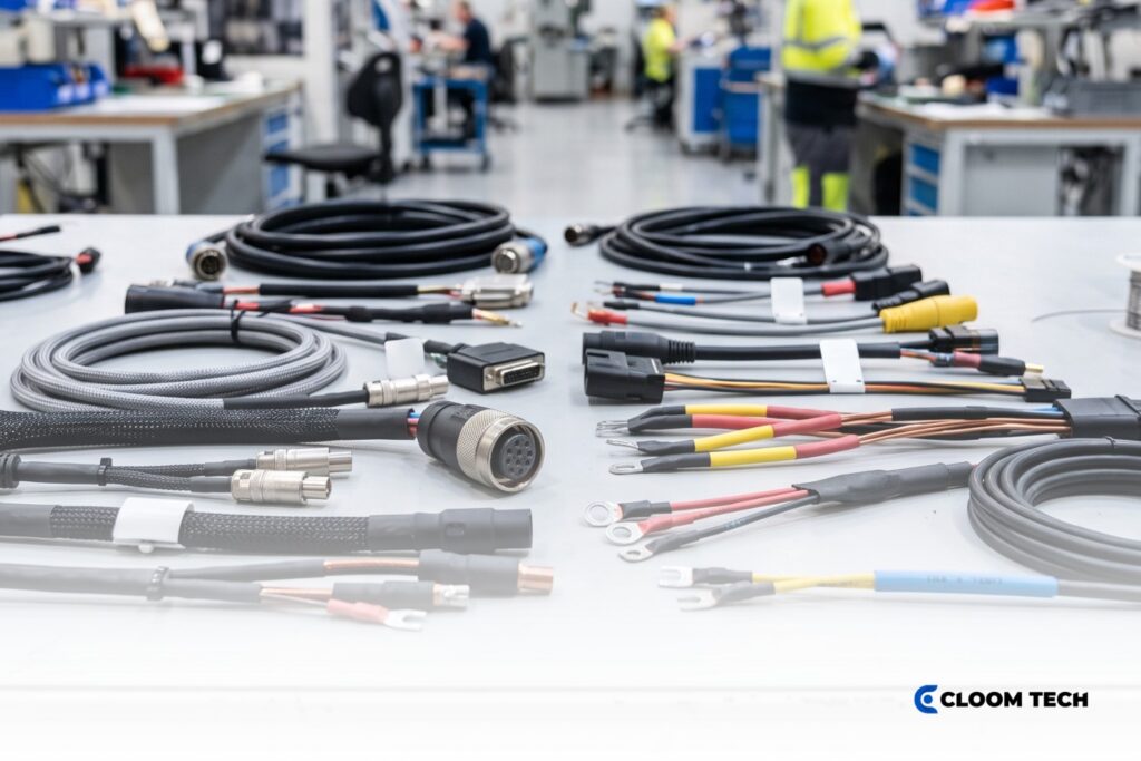
A drag chain cable can develop conductor breaks, shield damage, or jacket wear under repeated motion. These faults may interrupt power or signal transmission, stop automated equipment, and create unplanned maintenance work. A cycle rating alone can’t predict service life, as it reflects a defined test setup. Bend radius, carrier fill, travel distance, acceleration, and environmental exposure may differ in production.
For that reason, selecting a continuous flex cable starts with the machine’s actual motion profile rather than the largest cycle figure. Engineers must distinguish repeated bending from torsion, then match the cable and carrier to that movement. At the same time, conductor stranding, jacket material, and shielding must tolerate the resulting mechanical stress. Together, these factors determine whether the complete assembly is suited to its operating conditions.
What Flex-Cycle Ratings Actually Tell You
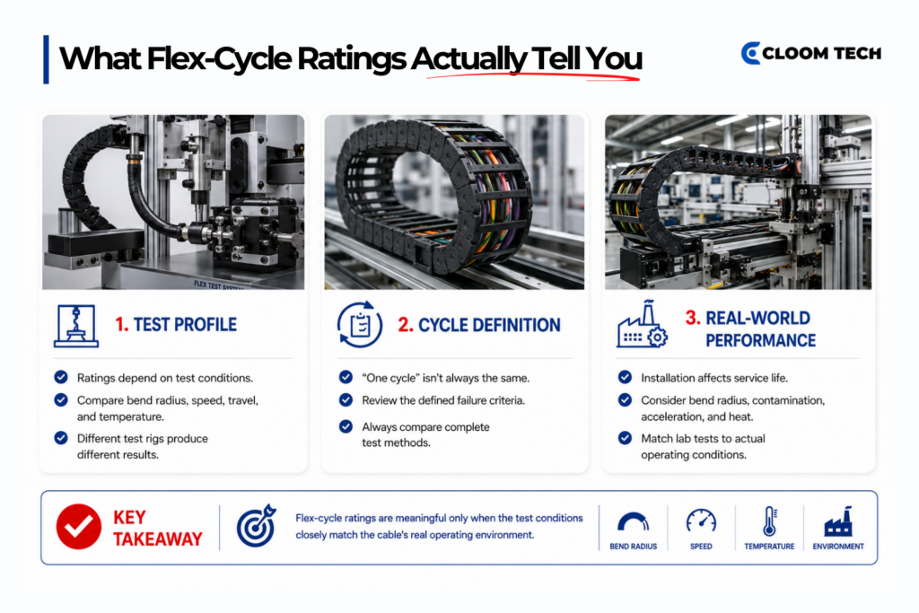
Flex-cycle ratings describe cable performance under stated test conditions, not a universal operating life. Their value depends on the test profile and the application data supplied with the result.
The Test Profile Defines the Rating
A useful rating identifies bend radius, travel, speed, acceleration, temperature, and failure criteria. Without those details, two identical cycle figures may represent substantially different mechanical demands.
Test equipment changes the applied stress. Alternating-bend rigs move a specimen around reels, while linear carrier rigs reproduce back-and-forth travel. Torsion rigs rotate the cable around its axis, and combined-motion equipment adds bending. These dynamic cable testing configurations load conductors, shields, and jackets in different ways.
Cycle Definitions and Endpoints Need Context
One cycle may refer to a single stroke or a complete out-and-back movement. Test documentation must define that movement and the failure endpoint, such as conductor rupture, insulation damage, or an electrical change. Motion-cable test terms lack complete standardization, which limits the value of a bare “millions of cycles” claim.
Confidence in cycle data depends partly on equipment calibration, personnel training, procedures, and consistent use of results. Independent process verification evaluates these controls, though one laboratory outcome can’t represent every installation.
Field Conditions Can Change the Service Life
Even detailed laboratory results need an application context. A correctly installed drag chain cable may face tighter bends, higher fill, contamination, or different temperatures than its test specimen. Bend radius, distance, acceleration, speed, and weight should accompany motion-category cycle ranges during comparison.
Engineers should treat a continuous flex cable rating as evidence tied to a defined motion envelope. The closest test profile offers the most relevant comparison. Substantial differences call for application-specific review or additional validation.
Continuous Flex vs. Torsional Flex
Continuous bending and torsion impose different mechanical loads, so a single cable rating can’t represent both. The cable construction must match how each machine segment moves.
Continuous Flex Controls Repeated Bending
A continuous flex cable suits controlled back-and-forth movement in a carrier. Linear bending stretches the outside of the cable while compressing its inside radius. Its components need a stable geometry as the cable follows that repeated path.
Fine conductor strands, short lay lengths, and pressure-extruded support layers can distribute bending forces while limiting internal movement. Physical softness alone doesn’t establish this capability, because different cable types exhibit different motion properties.
Torsional Flex Accommodates Axial Rotation
Torsion-rated cable allows controlled twisting over a specified length. The movement forces conductors, shields, and fillers to redistribute stress through the cable body. Each component must accommodate rotation without bunching or migrating.
A cable that survives repeated linear bending can still develop corkscrewing, shield damage, or conductor stress when a robot joint twists it. The reverse mismatch creates similar problems. Torsion-rated construction may tolerate axial rotation yet lack the abrasion resistance needed for millions of carrier strokes.
Combined Motion Requires Separate Limits
Robot dress packs may bend during arm extension while twisting around several axes. A dual-rated product needs stated limits for torsion angle, reference length, bend radius, and cycle conditions. A general flexible rating can’t substitute for those values.
Before specifying a drag chain cable, map every moving segment separately. Record whether each segment bends, twists, or combines both actions. Then capture the angle, radius, stroke, speed, acceleration, and cycles per operating period. This motion map separates carrier applications from routing and strain-relief concerns in robotic wire harness manufacturing.
The Design Rules
Bend radius, carrier fill, travel, and acceleration define the mechanical envelope for moving cable. Each value must come from the selected cable and carrier documentation because generic multipliers can’t represent every construction.
| Rule | Specification basis | Consequence of mismatch |
|---|---|---|
| Bend radius | Use the larger minimum radius required by the cable or carrier. Measure cable diameter using the supplier’s stated method. | A tighter bend increases strand elongation, conductor compression, and jacket stress during every stroke. |
| Carrier fill | Maintain the cable-specific clearance required by the carrier supplier. Separate incompatible diameters or media where the filling rules require dividers. | Crowding restricts movement, increases rubbing, and allows cables to push against the carrier or one another. |
| Travel length | Match carrier configuration, support method, and cable rating to the complete stroke. Long travel may require gliding operation, guidance, and different wear allowances. | An unsupported or unsuitable arrangement can increase friction, sag, tensile load, and carrier wear. |
| Speed and acceleration | Compare both values with the tested cable range and the carrier’s dynamic limits. Include abrupt direction changes in the motion profile. | Higher dynamic loads can increase tensile forces, component migration, and impact at reversal points. |
Bend Radius Follows the Stiffest Service
The stiffest installed service can set the minimum carrier radius. A cable drag chain should never force any cable or hose below its dynamic minimum. An increasing radius may require more installation space, yet it reduces the strain imposed during each bend.
Clearance Matters More than A Universal Fill Percentage
Carrier fill requires more detail than a single cross-sectional percentage. Round electrical cables need defined clearance, while separators can prevent interference. Supplier-specific spacing gives cables room to move without crossing, binding, or rubbing excessively.
Different Cable Diameters May Require Separation
Cable diameter differences matter within the same compartment. Large and small services can move at different rates, allowing one item to trap or ride over another. Separators or shelves maintain defined paths when the supplier’s sizing rules call for them. Hydraulic or pneumatic hoses may require greater clearance than electrical lines because pressure changes can alter their dimensions.
Carrier Orientation Changes Support Requirements
The selected drag chain cable carrier must suit the mounting orientation and available support. Horizontal long travel, vertical travel, side-mounted movement, and rotary travel create different weight and guidance demands. For that reason, the machine specification should record travel, unsupported span, moving mass, installation orientation, and expected environment together.
Cable Construction for Motion
Motion performance depends on how the conductor, stranding, internal support, shield, and jacket work together. A single feature can’t establish flex life because each layer experiences different mechanical stress.
Fine Stranding Distributes the Bending Stress
Fine-conductor strands distribute bending across more individual wires than coarse-strand conductors. International Electrotechnical Commission (IEC) 60228 Class 6 conductors use finer strands than Class 5 conductors, although conductor class alone doesn’t prove suitability. The completed cable still needs a strand arrangement and lay length matched to its movement.
Internal geometry controls how those conductors share force. Short lay lengths help each conductor change position over a shorter distance. A tension-resistant center and layered or bundled stranding can balance loading across the bend. Pressure-extruded inner layers can limit component movement and support the shield.
Jacket Compounds Match Environmental Exposure
Jacket choice starts with the operating environment and motion demand. Polyvinyl chloride (PVC) offers a cost-effective option for many moderate industrial conditions. Polyurethane (PUR) provides stronger abrasion, oil, and chemical resistance for harsher moving environments. Thermoplastic elastomer (TPE) can cover broader temperature or high-abrasion demands, depending on the specific compound.
These material names describe families rather than identical formulations. Temperature range, flame behavior, oil resistance, and chemical compatibility still require product-level data. The differences among PVC, PUR, and TPE support early screening, while the final choice must follow the actual exposure profile.
Flex-rated Shielding Maintains Electrical Performance
Shielding adds another mechanical system around the conductors. A flex-rated braid uses wire geometry and braid angles that accommodate repeated movement while maintaining electrical coverage. Foil can improve coverage at selected frequencies, yet unsupported foil may fatigue under repeated bending. Hybrid shield structures need flex-rated materials and controlled internal support.
Termination details influence the shield’s survival. The shield transition, connector backshell, and strain relief should avoid a sharp stiffness change near the moving boundary. Otherwise, bending concentrates at the termination rather than spreading through the intended flex zone.
A continuous flex cable specification should list electrical needs, motion, environment, shield performance, and termination geometry together. Selecting only by jacket material or conductor class leaves other failure paths unaddressed.
Selecting the Drag Chain and Cable Together
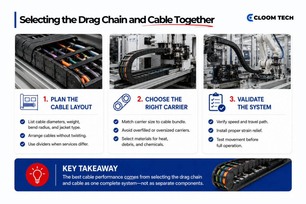
Cable and carrier selection must be made as a single system decision. The carrier controls bend radius, separation, support, and travel path. Each installed service contributes diameter, weight, stiffness, and clearance requirements.
Start With the Installed Services
Start with a complete cable and hose schedule. Record outside diameters, minimum dynamic radii, weights, jacket materials, and separation needs. The stiffest service usually sets the minimum carrier radius, while the total package determines the inner height and width.
Next, place each service within the cable drag chain using the carrier supplier’s filling rules. Cables should lie beside one another in defined paths without twisting around each other. Dividers become appropriate when diameter differences, incompatible media, or movement patterns could cause interference.
Match The Carrier to the Motion Path
The drag chain cable carrier then needs enough capacity without excessive unused space. An undersized cavity crowds the services and raises contact forces. An oversized cavity permits uncontrolled movement, which can increase impact and abrasion during acceleration or direction changes.
Carrier construction must suit surrounding chips, washdown, chemicals, temperature, and electrostatic requirements. Open carriers provide access and airflow, while enclosed arrangements offer greater debris protection.
Mounting geometry comes next. Fixed-point location, moving-end attachment, guide troughs, and support surfaces affect how the carrier travels. The cable length within the system must accommodate the carrier path without pulling at either termination. Strain relief belongs at the specified fixed and moving points, outside the controlled bend where applicable.
Validate The Complete Moving System
Finally, compare the complete arrangement with speed, acceleration, and duty-cycle requirements. Compatible drag-chain components can reduce malfunctions that interrupt production. The broader selection process complements the application coverage on robotic wire harnesses without duplicating its manufacturing focus.
A matched drag chain cable and carrier still require correct installation. Prevent cable twist during loading, maintain the specified clearances, and verify free movement through the full stroke. Commissioning should include slow travel, visual observation, and checks at reversal points before full-speed operation.
Common Failure Modes
Motion-cable damage patterns often reveal which mechanical condition needs correction. Replacing the failed cable without addressing that condition can reproduce the same fault.
- Conductor breakage: Repeated bending below the permitted radius, excessive tensile loading, or unsuitable stranding can fracture individual wires. Resistance may rise before the conductor opens completely.
- Corkscrewing: Torsion, improper installation or internal component migration can deform the cable into a spiral. The condition indicates that the cable can’t redistribute the applied mechanical stress correctly.
- Jacket abrasion: Crowding, inadequate separation, or contact with a rough carrier surface can wear the outer sheath. Debris inside a cable drag chain may accelerate the damage.
- Shield degradation: Repeated bending can break braid wires or fatigue foil, reducing shield continuity. Poor support near terminations can concentrate the movement in a short section.
- Cable migration: Incorrect length, missing strain relief, or unsuitable clearance can let cable move longitudinally. That movement may pull terminations or bunch cable near the carrier’s bend.
- Intermittent communication: Conductor fatigue, shield damage, or changing geometry can disturb signal integrity before complete electrical failure. Motion-correlated faults often appear only at certain positions or speeds.
Inspection should begin with the damage location and operating position. Wear along the full length of the jacket suggests ongoing contact, while damage near one end points toward strain relief or a stiffness transition. Failure at the bend can indicate concerns about radius, construction, or repeated loading.
Maintenance records add another layer of evidence. Track machine position, cycle count, operating temperature, recent speed changes, and contaminant exposure when faults appear. Those observations help connect the visible symptom to a changed operating condition.
A replacement continuous flex cable should match the corrected motion and environment, rather than merely duplicating the failed part number. The drag chain cable carrier may need to be adjusted for separation, support, or radius when it contributed to the damage. Slow-motion observation after maintenance can confirm free travel before normal production resumes.
Build a Motion-Rated Assembly With Cloom Tech
Cloom Tech manufactures custom wire harnesses and cable assemblies for continuous-motion applications using your pre-existing drawings and application requirements. Our team can review bend radius, carrier dimensions, material choices, shielding, and termination details during a Design for Manufacturability review.
Facilities in China and the Philippines support prototypes through mass production in accordance with ISO 9001, IATF 16949, and IPC/WHMA-A-620 requirements. We provide transparent pricing, global material sourcing, and internal and third-party inspections.
Contact us to discuss a motion-rated assembly for your operating environment and production volume.
Robotics & Industrial Automation Cable Assemblies FAQs
What Test Details Should Accompany a Flex-Cycle Rating?
A useful flex-cycle rating should identify the motion method, bend radius, travel, speed, acceleration, temperature, and cycle definition. It should state the tested cable construction and failure endpoint. These details let engineers compare the laboratory profile with their application instead of treating the cycle number as a standalone promise.
Can Power and Data Cables Share the Same Carrier?
Power and data cables can share a carrier when the cable specifications, electromagnetic compatibility needs, and carrier rules support that arrangement. Separation or shielding may become necessary when power conductors could interfere with sensitive signals. The available space must still provide the required clearance for every installed service.
A drag chain cable carrier can use dividers to maintain separation when the supplier permits both cable types in a single system.
How does Longer Travel Affect Carrier Selection?
Longer travel can change the carrier from unsupported movement to gliding operation, which adds guidance, friction, and wear considerations. The carrier supplier should confirm support length, guide trough geometry, moving mass, speed, and acceleration. Cable ratings must cover the full travel because distance forms part of the tested motion envelope.
When does an Application Need a Custom Flex-Rated Assembly?
A custom flex-rated assembly becomes appropriate when catalog products don’t match the combined electrical, motion, environmental, and termination requirements. Examples include mixed power and signal circuits, unusual connector interfaces, restricted routing, or application-specific lengths. The specification should define the cable drag chain, motion profile, exposure conditions, and required tests before manufacture.
Back to Top: Robotics & Industrial Automation Cable Assemblies: Flex-Cycle Ratings and Drag-Chain Selection
