


Every wiring fault in a low-voltage DC harness – whether in a vehicle, trailer, or piece of equipment – belongs to one of four categories. Identifying the fault type before selecting a meter reduces diagnosis time and prevents misleading readings.
A systematic approach to testing wiring combines continuity checks, short-circuit isolation, insulation resistance measurements, and intermittent fault detection. Technicians use a digital multimeter (DMM) for continuity, resistance, and voltage-drop measurements, while a megohmmeter evaluates insulation that a DMM can’t assess adequately.
All continuity, resistance, and insulation procedures require a de-energized harness disconnected from attached components. Only the identified live-voltage and voltage-drop procedures require an energized circuit under controlled conditions.
The Four Wiring Fault Types
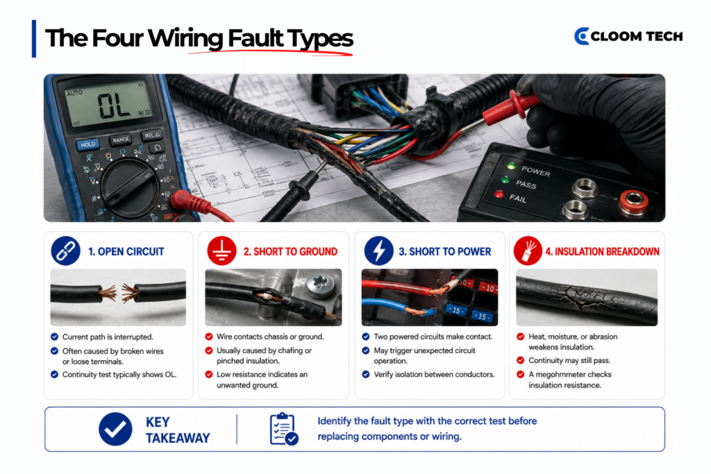
The four wiring fault types are open circuits, short-to-ground faults, short-to-power faults, and insulation breakdown. Since different faults can produce similar circuit behavior, you’ll need the correct meter test to distinguish them.
Open Circuits
An open circuit breaks the conductor path, preventing current from reaching the load. Vibration, corrosion, backed-out terminals, and repeated movement can interrupt that path.
When testing wiring for an open circuit, a complete break normally produces an over-limit (OL) reading during a de-energized end-to-end continuity test. A partially fractured conductor may still show continuity while stationary and open only during movement.
A high-resistance terminal may carry the DMM’s small test current while restricting the load’s operating current.
Short-to-Ground Faults
A short-to-ground fault connects a conductor to the chassis, frame, or another grounded surface through chafing, pinching, or conductive contamination.
An isolated, ungrounded conductor should show OL when tested against ground. Low resistance suggests an unwanted contact when the circuit map shows no connected load providing a legitimate ground path. Depending on the circuit and fault resistance, a fuse may open immediately, or the fault may appear only during movement.
Short-to-Power Faults
A short-to-power fault connects one circuit to another conductor that carries voltage during operation. The affected circuit may activate unexpectedly or operate with an unrelated circuit.
Heat-damaged insulation, moisture, and compressed conductors can cause these faults. Check for continuity between conductors that should remain separate on a de-energized harness.
The term “short-to-power” refers to a fault where a conductor makes unwanted contact with a power-carrying wire; the circuit diagram is essential for identifying which terminal pairs must remain isolated.
Insulation Breakdown
Insulation breakdown reduces electrical separation between conductors or between a conductor and ground. Moisture, contamination, heat cycling, and mechanical abrasion can weaken insulation before a direct short develops.
The conductor may pass continuity because its intended path remains intact, while a DMM’s low voltage may miss leakage. A megohmmeter applies a controlled DC voltage to measure insulation resistance.
Continuity Testing, Step by Step
Testing wiring for continuity confirms whether an isolated conductor provides an intact path between specified terminals. Reliable results depend on correct pin identification, firm probe contact, and resistance limits suited to the conductor.
Setup: De-energize and Isolate
Complete four preparation checks before selecting continuity or resistance mode:
- Disconnect the power source: Unplug both ends of the conductor and remove attached components that could create parallel paths between the measurement points.
- Verify the absence of voltage: Confirm that the circuit is de-energized because external voltage can damage the DMM and invalidate resistance readings.
- Confirm the pin positions: Review the circuit map and connector orientation, as diagrams may show the mating face or the wire-entry side.
- Compensate for test leads: Touch the probes together and record their resistance or use the meter’s relative function to remove that value from the conductor measurement.
Probing: Pin to pin
Set the DMM to continuity mode for a preliminary check or select the lowest suitable resistance range for a measured result. A tone only indicates that resistance falls below the meter’s internal beep threshold, which may exceed the circuit’s acceptable resistance.
Place one probe on the specified terminal at the first connector, then touch the second probe to the corresponding terminal at the opposite end. Avoid spreading, bending, or scratching the contact surfaces.
A stable reading near the compensated test-lead resistance indicates a low-resistance path, though acceptance is determined by the applicable requirements. After lead compensation, 0.5 Ω or less may suit a short, heavier-gauge conductor, while longer or thinner conductors produce more resistance.
An OL reading indicates that the resistance exceeds the selected range, or no complete path exists; confirm the range, pins, and probe contact.
Locating the Break
Divide the conductor into sections using approved intermediate connectors, splices, or access points. If the first segment shows continuity and the next returns OL, the break lies in the second segment. Continue dividing that section until the test isolates the damaged area.
Avoid puncturing intact insulation because probe holes can damage strands and admit moisture. Without intermediate connectors, inspect connector entries, clamps, bends, and abrasion zones.
Wiggle Test for Intermittent Opens
Keep the DMM connected across the isolated conductor while gently moving one harness section at a time. Stabilize both probes so movement at the test points doesn’t create a false interruption.
Move the bundle within its normal range, then check the connector housing and strain relief. OL indicates a movement-sensitive open, while smaller changes may identify damaged strands or unstable contact.
Diagnosing Shorts
When testing wiring for shorts, technicians look for continuity between points that should remain electrically isolated. Loads, modules, and shared paths must be disconnected before a low-resistance reading can confirm a fault.
Short-to-Ground Check
De-energize the harness and disconnect the suspect circuit at both ends, including lamps, brake magnets, coils, and other components that provide an intended ground path.
Connect one probe to the suspect conductor and place the other on the specified harness ground or on a verified clean chassis point. An isolated, ungrounded conductor should return OL, while low resistance indicates a possible ground connection after accounting for test leads and remaining parallel paths.
If a load remains connected, finite resistance may be normal, so disconnect it before repeating the measurement. Inspect brackets, clips, and pass-through openings for abrasion.
Short-to-Adjacent-Wire Check
Probe the suspect conductor against each connector pin to ensure each remains electrically separate. Every unrelated pair should return OL after connected components have been removed.
A low reading identifies an unwanted path, but not its location. Don’t apply a universal threshold because length, gauge, circuit arrangement, and lead resistance affect the result.
Isolating the Short
Use a section-by-section sequence after confirming the unwanted path:
- Separate an intermediate connection: Disconnect an approved junction and repeat the measurement on both sections.
- Follow the remaining reading: Continue dividing the side that retains the unwanted path until the result changes to OL.
- Isolate individual branches: Disconnect one branch at a time and label each connector so final reconnection remains traceable.
- Check documented splices: Confirm shared connections before treating continuity between two conductors as a fault.
Insulation Resistance Testing
When testing wiring for insulation breakdown, insulation resistance testing applies a specified DC voltage across isolated insulation and measures the resulting resistance. It detects moisture, contamination, and progressive deterioration that continuity testing may miss.
Why a Multimeter Falls Short
A DMM uses a small signal to measure resistance, allowing it to identify a direct conductor-to-conductor or conductor-to-ground short. However, it can’t characterize insulation under higher electrical stress.
A megohmmeter applies a controlled voltage and measures leakage in megohms (MΩ) or higher. A harness can pass continuity yet return insulation resistance below its minimum.
Hipot and insulation resistance testing evaluate different properties:
- Hipot testing: Confirms whether insulation withstands an elevated voltage without excessive leakage, arcing, or breakdown.
- Insulation resistance testing: Quantifies resistance across insulation to identify moisture, contamination, and gradual deterioration.
Running the Test
Insulation resistance testing follows a controlled sequence because the instrument applies a higher voltage than a standard DMM:
- Isolate the harness: De-energize the circuit and disconnect modules, sensors, suppression devices, and other voltage-sensitive components.
- Confirm the requirements: Obtain the specified voltage, duration, connection arrangement, and pass limit for the harness.
- Connect the instrument: Place the leads between specified conductors or between one conductor and the required ground or shield.
- Configure unused conductors: Leave as is or connect them according to the approved test method.
- Apply the test voltage: Hold it for the specified period and record resistance at the required measurement time.
- Discharge the harness: Follow the instrument’s discharge procedure and verify a safe voltage before handling terminals.
Don’t select 250 V, 500 V or another setting without checking the harness specification and component ratings. Only trained personnel should perform the test and respond to breakdown or unstable leakage.
Reading the Results
Compare the result with the minimum specified for the harness, the conductor pair and the test voltage, as no universal MΩ threshold applies. Record the conditions that affect interpretation:
- Electrical conditions: Test voltage, duration, and conductor arrangement.
- Harness conditions: Length, conductor configuration, and insulation material.
- Environmental conditions: Temperature and humidity during testing.
A low result may indicate moisture, contamination, damaged insulation, or inadequate sealing. Repeat trend measurements under comparable conditions.
Intermittent Faults
When testing wiring for intermittent faults, technicians need controlled movement tests and, where appropriate, voltage-drop measurements under load. Static continuity checks may miss failures that appear only during vibration, temperature changes, or current flow.
The Wiggle Test
Connect the DMM across the isolated conductor in resistance mode and secure the probes, as probe movement can simulate the fault.
Move along the harness in short sections and apply controlled pressure near strain reliefs. OL identifies an open, while increased resistance may indicate damaged strands or poor terminal contact.
Voltage-Drop Testing Under Load
Voltage-drop testing measures the voltage lost across a conductor, crimp, or connector while operating current passes through it. This procedure requires an energized circuit under a defined load.
Set the DMM to DC voltage and place one probe on each side of the suspect section. Operate the circuit under the same load that produces the fault because a low-current test may not reveal significant resistance.
Compare the drop with the circuit specification under the stated current and temperature. Monitor the meter while moving the suspect section, then test the conductor and connector separately.
Testing a Trailer Wiring Harness
Testing a trailer wiring harness requires separate checks on the passive trailer plug and energized vehicle socket. Start with the trailer ground before checking shorts, continuity, and vehicle-side voltage.
Connector layouts vary by standard, manufacturer, and region, while wire color alone can’t reliably identify a circuit. Verify every pin against the applicable connector diagram before trailer wiring testing.
Identify the Circuits
A common seven-way connector carries these circuits, although their pin positions must be confirmed against the applicable diagram:
- Ground: Provides the electrical return path.
- Running lights: Supplies marker, tail, and license-plate lights.
- Left turn and brake: Operates the left signal and brake light.
- Right turn and brake: Operates the right signal and brake light.
- Electric brakes: Carries the brake-controller output.
- Auxiliary power: Supplies a constant or switched 12 V feed, depending on the vehicle.
- Reverse lights: Activates the reverse-light circuit when equipped.
Ground Circuit First
Disconnect the trailer from the tow vehicle, set the DMM to resistance mode, and measure between the ground pin and a clean frame point. Compensate for test-lead resistance before evaluating the result.
A stable value near the expected ground-conductor resistance indicates a low-resistance path. Gauge, length, terminal condition, and manufacturer requirements determine acceptance.
Short-to-Ground Check on Each Circuit
Disconnect lamps, brake magnets, and other loads because they create legitimate paths to ground. Probe each isolated circuit pin against the ground pin or frame, expecting OL where the circuit diagram requires electrical separation.
A low reading identifies a possible ground path. Disconnect branch connectors individually to locate the affected section, especially near frame openings and exposed underside runs.
Individual Circuit Continuity
Probe each trailer-plug pin against the disconnected terminal at its assigned lamp or component. Stable low resistance confirms an intact path, while OL indicates an open. Compare the value with the expected resistance for the conductor’s gauge, length, and terminal arrangement.
For an isolated electric brake magnet, many 10-inch and 12-inch assemblies measure approximately 3.0–3.8 Ω per magnet. The acceptable range depends on the manufacturer, model, and temperature.
Multiple magnets connected in parallel have a lower total resistance than a single isolated magnet. The sequence for testing a trailer wiring harness should isolate each magnet when a combined reading falls outside the specified circuit value.
Live Vehicle-Socket Verification
Vehicle-socket voltage testing requires an energized low-voltage circuit. Keep the trailer disconnected unless the vehicle procedure requires a load or an approved test adapter.
Set the DMM to DC voltage, use the verified socket ground as the reference, and activate one vehicle function at a time. A conventional 12 V lighting circuit may show approximately 11–14 V when active, depending on battery condition, charging state, and test load.
The turn and brake circuits may pulse, and the brake-controller output will vary with its gain setting. Be aware that some modern vehicles produce approximately 5–7 V diagnostic signals on these circuits even without a trailer connected.
Repeat trailer wiring testing with the approved load or adapter when the vehicle requires trailer detection. An unloaded measurement may not reproduce the operating condition that triggered the fault.
How Production Harnesses are Tested

Production testing verifies every finished harness against approved connection requirements and acceptance criteria. It differs from field-testing wiring with a multimeter, which targets individual circuits after an operating fault occurs.
Electrical Connection Testing
Harness-specific requirements identify every required path and terminal pair that must remain isolated. Test fixtures provide access without repeated direct probing.
Cloom Tech performs full electrical testing on every finished harness before shipment, checking conductor paths and connection integrity against applicable product requirements.
These checks can identify:
- Open circuits: An expected connection is absent, or the connection exceeds its specified resistance limit.
- Short circuits: Continuity appears between terminals that should remain isolated.
- Miswires: A conductor reaches a terminal outside its assigned connection requirements.
- Incomplete terminations: A loose or partially seated terminal produces an unstable or high-resistance path.
Resistance Limits
Continuity and short-circuit requirements vary by IPC/WHMA-A-620 product class, customer agreement, and the applicable test table. The testing process must use the requirements assigned to the assembly.
Class 1 and Class 2 assemblies may be tested against applicable tester thresholds or customer-defined limits. Without agreed requirements, Class 3 guidance has used 2 Ω or 1 Ω plus the conductor’s actual resistance.
The current standard revision, customer drawing, and product specification govern acceptance. Four-wire Kelvin measurement can remove fixture-lead resistance, although mating-contact resistance remains.
Hipot and Insulation Resistance Testing
Production plans add hipot and insulation resistance testing when the product specification requires them. Hipot applies an elevated voltage and monitors leakage or breakdown, while insulation resistance testing quantifies the insulation’s resistance.
Neither method uses a universal limit. Dwell times, ramp settings, and discharge periods must follow approved requirements and protect voltage-sensitive components.
Pull-Force Testing
Pull-force testing verifies crimp-process strength using prepared samples that combine the specified terminal, conductor material, wire gauge, and crimp settings.
A pull tester applies force until a defined endpoint occurs, and the recorded force must meet the applicable minimum.
Since the procedure damages the sample, manufacturers use it during setup and process validation rather than on every finished termination.
Discuss Your Wire Harness Testing Requirements
Cloom Tech manufactures custom wire harnesses and cable assemblies for automotive, industrial equipment, consumer electronics, telecommunications, and medical device applications.
Our teams in China and the Philippines support prototypes through mass production, with approximately 2–3-week prototype and 4–5-week production lead times. We apply full electrical testing to every finished harness and follow ISO 9001, IATF 16949, and IPC/WHMA-A-620 requirements. You’ll receive Design for Manufacturability (DFM) feedback on pre-existing drawings, material selection, and production efficiency.
Contact us to discuss your specifications, volumes, testing criteria, and project timeline.
Wiring Fault Diagnosis FAQs
What is a normal continuity reading for a good wire?
There is no single “normal” reading. For a good wire, the measured resistance should approach its calculated value (based on gauge, length, material, and temperature) after compensating for test lead resistance.
A continuity beep only confirms that the reading falls below the meter’s preset audible threshold, which may exceed the circuit’s acceptance limit.
Why does a circuit pass continuity testing but fail under load?
This often indicates a high-resistance fault. A damaged conductor might carry the DMM’s small test current (showing continuity) but be unable to handle the higher operating current required by the load. A voltage-drop test under load is needed to detect this type of failure.
What readings should I expect on a 7-pin trailer connector?
A conventional 12 V lighting circuit may show approximately 11–14 V, while some unloaded systems produce diagnostic signals of approximately 5–7 V.
An isolated 10-inch or 12-inch brake magnet may measure approximately 3.0–3.8 Ω, depending on its manufacturer, model, and temperature. Parallel magnets produce a lower combined resistance.
When is a megohmmeter needed for diagnosing a trailer harness?
Use a megohmmeter when insulation deterioration remains suspected, selecting the voltage from applicable requirements and disconnecting sensitive equipment.
Back to Top: Wiring Fault Diagnosis: How to Test Wiring for Continuity, Shorts & Insulation Faults
